23 July 2015[This page was recovered from the TheStuffWeBuild WordPress Archive and adapted for this site in 2025.]
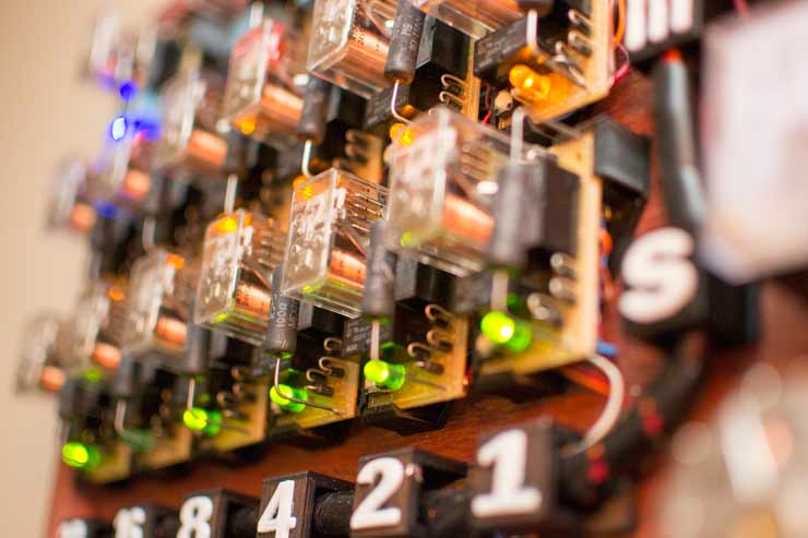
After years of waiting to find the right hardware, I have finally found the time and the opportunity to build my own digital mechanical clock that uses absolutely no transistors or ICs. Its technology is reminiscent of the early relay computers from many decades ago. It uses 67 relays arranged in such a way to create 21 identical flip-flop logic circuits.
All of this logic works together to accurately keep track of the time 24 hours a day. A synchronous motor and gearbox references the 60Hz main frequency in such a way to deliver a 1PPS signal to the logic gates. From here, a 6-bit binary "register" increments up by one unit each second. Once it reaches 60, an additional flip-flop circuit simultaneously clears this register and adds one unit to the minutes row.
A similar process also happens between the minutes, hours, and AM/PM bit.
How to read this clock
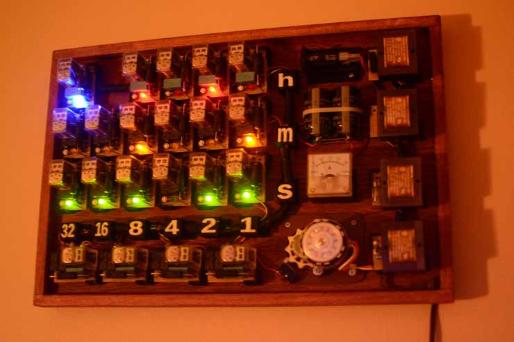
Don't know how to read binary? It's easy! A numerical guide is given below the display area to signify the decimal value of each column.
Take this image above for example. If the blue light is on, it means its currently PM. The red, yellow, and green lights signify hours, minutes, and seconds respectively.
The hours row currently has the binary value 1010. To convert that to decimal, add 8+2. This gives you 10 for the hours.
The minutes row has the value 001001. If you add up the bits that are on, you get 9 for the minutes.
So the time seen in the picture above is 10:09pm. The seconds row is insignificant for most cases, still we can read that too. It shows a binary value of 111011. Follow the columns down and you'll see that you'll have to add 32+16+8+2+1, which equals 59.
Would you look at that, it's 10:10! Do you ever notice that every watch and clock ad, regardless of the company or model always shows the time as 10:10? It's true! Take a look next time you see one of those ads.
*The digital clock to the left is not part of this project. It is only shown for comparison.
This Electromechanical Relay Clock uses 67 relays arranged in 21 flip-flop logic circuits. It is in essence a computer that can add, compare, and clear various registers in order to keep track of the time.
It was inspired largely by the electromechanical relay computers from several decades ago as well as the many other hobbyist projects seen today.
In addition to the 67 relays (21 4PDT and 46 DPDT), this circuit also uses a total of 237 diodes, 42 resistors, and well over a hundred feet of wire across nearly 1,400 solder connections. There are absolutely no transistor junctions or integrated circuits here, and the only two capacitors are those used for filtering the 24 volt supply voltage.
Every component in the circuit is running in-spec according to their datasheets (unlike some other simplified relay logic circuits). Still, a bi-metal circuit breaker and a small fuse insure safe, continuous operation.
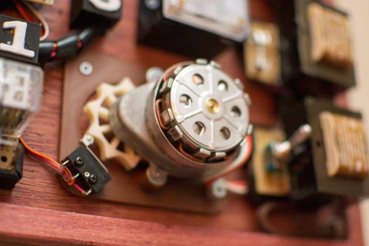
The 1pps output comes from a synchronous timing motor/gearbox that references the 60Hz mains frequency and rotates a 3D printed ten-pointed cog at exactly 6RPM. In a sense, this is the computer's clock, running at a whopping 1 × 10⁻⁹ gigahertz.
The motor is a 600 Series Synchron C Mount type. Initial plans called for a synchronous microwave turntable motor of the same speed, however most were later found to lag behind by a few minutes every hour. This motor on the other hand is designed for use in such applications as analog clocks and chart recorders.
The project was first conceived from the inspiration of the various electromechanical computers throughout history and from intrepid hobbyists alike. Eventually, a couple dozen 4PDT relays were acquired and from that did the project begin.
Operation
The clock outputs three binary numbers (red, yellow, green) and one additional bit (blue) to signify AM/PM. To read this clock in decimal, look at any one row and add up only the columns that are illuminated. A numerical guide that values each column is shown below the display area.
Although the circuit is very large, all 21 relay modules are essentially alike. The four logic boards at the bottom however have an additional output relay in place of an LED. A more in-depth writeup of how to read binary is on this project's blog post: HERE.
Here is a short video highlighting the sheer excitement of this build:
In reality however, I would have to say the many hours of labor involved in this project was more zen then actual labor.
Design
A full schematic was not necessary for this project. Instead a derivative of Simon Winder's Edge triggered D type flip flop was used and referenced for each and every one of the 21 logic modules. Once one module was completed, all other subsequent ones were simply a copy of the previous.
I highly encourage you to take a look at Simon's awesome Relay Calculating Engine as it was large part of the inspiration for this project.
Here are two of his videos I watched many times over while designing my project: